The Prestidigitation Stirling Engine: Ten Horsepower from a Basement, Two Cantrips an Hour
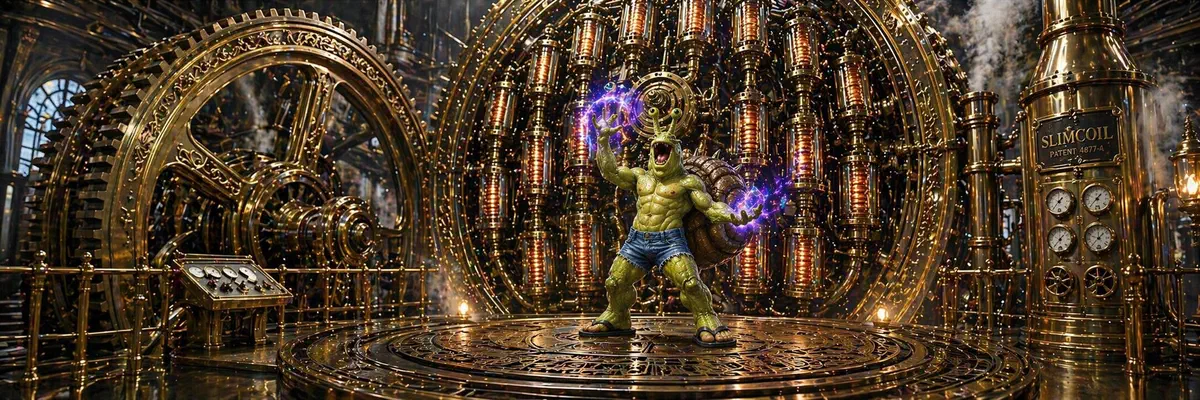
By Glorp Slimecoil — snelk, Path of Wild Magic barbarian, apprentice artificer, and certified disruptor of established industrial norms
On the barbarian half of my résumé: rage, grapples, and a handful of unlikely accomplishments — ceilings walked, thirty-foot sideways teleports through the Spirit Veil at my catfolk grandmother’s insistence, several things punched into the ground. Call me a barbarian. Fine.
The other half is artificer, the class every DM approves of on the assumption you’ll play a polite gnome with a clockwork pet. I am not a gnome. I am a half-snelk half-catfolk with a 16 STR and a +3 proficiency bonus, and I took Artificer for two reasons. First, a self-crafted repeating heavy crossbow and a defensive stack1 that turns a front-line barbarian into a tungsten ingot with opinions. Second: a Manifold Tool in the hands of someone who has actually read a thermodynamics textbook is one of the most dangerous things in the game.
What follows is the design for a power plant you can build with nothing but a cantrip and a decent forge, which is, I imagine, why my current DM is going to stop speaking to me any minute now.
The cantrip that broke economics
Prestidigitation is a transmutation cantrip most people cast to clean their boots or warm their soup. The text on my character sheet reads:
Prestidigitation
Casting Time: Action
Range: 10 feet
Components: V, S
Duration: Up to 1 hour
You create one of the following magical effects within range:
- Minor Sensation. You create an instantaneous, harmless sensory effect, such as a shower of sparks, a puff of wind, faint musical notes, or a strange odor.
- Fire Manipulation. You instantaneously light or snuff out a candle, a torch, or a small campfire.
- Minor Cleaning. You instantaneously clean or soil an object no larger than 1 cubic foot.
- Minor Alteration. You chill, warm, or flavor up to 1 cubic foot of nonliving material for 1 hour.
- Minor Making. You make a color, a small mark, or a symbol appear on an object or a surface for 1 hour.
- Minor Conjuration. You create a nonmagical trinket or an illusory image that can fit in your hand and that lasts until the end of your next turn.
If you cast this spell multiple times, you can have up to three of its non-instantaneous effects active at a time, and you can dismiss such an effect as an action.
Everybody focuses on “flavor” — oregano on the stew, vanilla in the wine — because it’s the silly one. Ignore it. The two words that matter are warm and chill: one cubic foot at 40 °C for an hour paired with another at 5 °C for an hour, which is a Maxwell demon with verbal and somatic components.
The spell doesn’t specify a final temperature, but most tables accept “warm” as around 40 °C (a hot bath, give or take) and “chill” as somewhere in the refrigerator range (5 °C). That’s a 35 K temperature gradient, maintained indefinitely by a cantrip that costs zero spell slots and has no daily limit. The magic is indifferent to heat flow: withdraw energy from the warm side and it stays warm; dump heat into the cold side and it stays cold.
You cannot, sadly, heat or chill the same cube twice (the “same effect doesn’t stack” rule would otherwise let you refrigerate molten lead), but two separate cubes are fair game.
Why Stirling, and why not steam
The canonical “prestidigitation exploit” thread on every D&D forum runs the same arc: warm 1 ft³ of water, try to run a steam engine, realize the spell doesn’t get things hot enough to boil, give up, post on Reddit.2 Those people have never heard of Robert Stirling, a Scottish minister who in 1816 built a heat engine that works on temperature differential rather than absolute temperature. A Stirling doesn’t care that 40 °C isn’t boiling; it cares about ΔT, and ΔT is all we have.
The theoretical ceiling is the Carnot efficiency:
η = 1 − Tc/Th
η = 1 − (278 K / 313 K) = 11.2%
Eleven percent sounds bad until you notice that the heat source is free, infinite, and has no fuel chain. A real Stirling with a good regenerator hits maybe 60–70% of Carnot, so call it ~7% wall-to-shaft efficiency. Modest, but the input is unlimited.
A note on portability. “Fits in a backpack” is still a lie, though a much smaller lie than the forum consensus would have you believe. Mark I comes in at around 40 kg / 88 lb dry, dominated by the cast-iron flywheel rim and the bronze cylinder walls; the beech-honeycomb heat exchangers (explained below) are a rounding error, and the frame is oak.
Forty kilograms is within carrying capacity for anyone with a 16 STR, which means me, holding it one-handed if I feel like being flashy. Moving five at once is where Tenser’s Floating Disk earns its slot: its 500 lb / 227 kg capacity swallows four engines plus a day’s rations with room to spare.
The aggressive weight-down came from two moves. The first and much larger one was deleting the copper heat exchangers, which by themselves accounted for over 500 kg in the paper design — more on that in the build section. The second, which mattered only once the copper was gone, was actually running the safety arithmetic on the cylinders, flywheel, and frame, each of which had been carrying orders of magnitude of “just in case” in their sketched margins. Both are in the build section below.
The build
I built the first prototype with nothing but a Manifold Tool: one common wondrous item, one attunement slot. Crafting is the whole point of the artificer class, so none of this is hidden lore. The Manifold Tool makes the project tractable: instead of a backpack full of Brewer’s Supplies, Tinker’s Tools, Smith’s, Mason’s, Glassblower’s, and Carpenter’s, I carry one device that becomes each of them in turn, granting me proficiency the moment I hold it. I can also replicate the Manifold Tool itself via Replicate Magic Item, the level-2 Artificer class feature in the 2024 Eberron: Forge of the Artificer rules, which materialises the entire apprentice-level craftsman skill tree out of a single common-magic-item slot.
Here is the Manifold Tool text:
Manifold Tool
Requires Attunement
This tool takes the form of a wrench, a screwdriver, or another basic tool. As a Magic action, you can touch the item and transform it into a type of Artisan’s Tools of your choice. Whatever form the tool takes, you have proficiency with it when you use it.
Any artisan’s tool with proficiency, on demand: Smith’s Tools for the cast-iron flywheel rim and bronze cylinder liners, Carpenter’s Tools for templating and carving the beech-honeycomb heat exchangers along with the oak frame and the wooden flywheel spokes (which makes Carpenter’s, not Smith’s, the load-bearing skill on this build), Mason’s for the stone foundation, Calligrapher’s so I can sign my name on the side in letters a foot tall. One common-rarity wondrous item turns a snelk barbarian into a full-service medieval machinist.
The engine is an alpha-type Stirling, 100 mm bore × 75 mm stroke, air at 1.5 atm, running at 6 Hz. The heat exchangers were where I almost made the most expensive mistake of my artificing career, so here’s the design history.
Every thread on the Scrivener’s-Net opens the same way: copper, obviously, because thermal conductivity. My first sketches agreed: two cubic feet of hammered copper finned to about 2 m² of surface area per side, 508 kg of raw copper gobbling most of the bill of materials and all of the portability budget. Once you commit to a third of a ton of copper inside the engine, the rest of the machine has to be sized to hold it up: the paper design accordingly called for a stone foundation anchored into the floor, cast-iron bracketry to hang the HX cans off, a heavy cast-iron bedplate under the cylinder assembly, and a correspondingly massive solid flywheel to match. The whole thing came in just shy of 600 kg — a stationary industrial installation, a mill-floor fixture, not a device any snelk was going to pick up. I spent a week optimising the fin geometry on the theory that vane thickness was the critical constraint, since thinner fins mean more surface area per kilogram, which means cheaper and lighter engines. The hand-beating limit on copper foil is about 50 µm, at which point a fin the size of my palm has the structural rigidity of a damp playing card and would crumple under 6 Hz gas scour inside a minute.
So I went shopping for alternatives. Gold leaf — the real stuff, the kind a Calishite gilder can beat to 100 nm in an afternoon — is 500 times thinner than hand-beatable copper. The arithmetic was startling: a square metre of 100 nm gold leaf masses about 2 g (~0.2 gp of bullion), while a square metre of 50 µm copper foil masses 448 g (~0.5 gp of raw copper). Gold, by the square metre, is cheaper than copper once you let it be as thin as it physically can be. I went to bed that night very pleased with myself.
Then I woke up and remembered that 100 nm gold leaf has the mechanical integrity of a moth wing. One cycle of 6 Hz gas flow at 1.5 atm turns the entire heat exchanger into confetti, and you can’t brace a film that thin into a finned structure because any brace thick enough to matter swamps the whole mass-saving argument. I was still sulking in this cul-de-sac when a sharper friend asked, quietly, why the gas face needed to be metal at all.
Read Prestidigitation again, slowly: “chill, warm, or flavor up to 1 cubic foot of nonliving material for 1 hour.” The spell is not heating a surface and letting heat conduct inward; it is holding every atom inside the cubic-foot volume at temperature, directly, by fiat, for the full hour. There is no temperature gradient inside the wall to conduct across. Fin efficiency doesn’t apply because there is no “root” of the fin; every point is simultaneously the root. Copper’s 400 W/m·K is doing zero work, because there is no conductive path for it to work across.
The only term still in the heat-transfer equation is the gas-side convective h, which depends on two things: flow geometry (Reynolds number, turbulence) and surface area. Neither depends on wall material. Whether the gas is licking copper, gold, or shellacked beech, it deposits its heat into a surface that magic is already holding at exactly the reservoir temperature.
So the Mark I heat exchangers are shellacked beech honeycomb: hexagonal cells about 2 mm across with 0.3 mm walls, carved on a templated hollowing jig and sealed with three coats of shellac to keep the wood dry and dimensionally stable in humid air. About 0.1 ft³ of actual wood per HX nests inside a 1 ft³ cantrip envelope. Surface area comes out to roughly 25 m² per side, an order of magnitude more than the copper design at 5% of the mass. Each HX weighs about 2 kg and costs about 6 gp in materials and a day of Carpenter’s-Tools work.
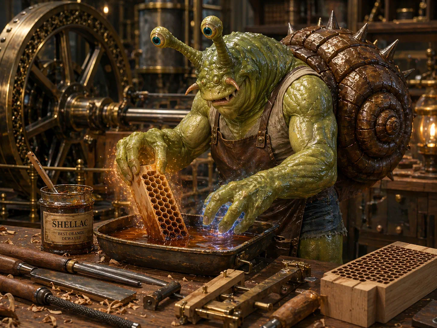
Self-portrait, third coat. Beech HX blanks get carved on the spindle-jig, then dipped and brushed with shellac three times — once per afternoon, drying overnight on the rack — which buys enough dimensional stability that seasonal humidity doesn't detune the gas-side boundary layers. One day of Carpenter's-Tools work per HX; twenty-four HXs for the full solo fleet.
This is the move that changes what the engine is. Swapping copper for beech takes total HX mass from 508 kg to about 4 kg per engine — a single decision that saves more weight than the entire rest of the built machine weighs finished. Once the heat exchangers stop being a third of a ton of metal, the whole premise of the stone foundation and the cast-iron bracketry evaporates: there is nothing heavy left to hold up, so the rest of the engine can be re-sized from scratch on its own modest loads. The paper design goes, in one step, from a mill-floor installation to something in the neighbourhood of one-person-portable. Everything further down in the build section — the hoop-stress arithmetic on the cylinders, the hoop-weighted flywheel, the oak frame replacing the cast-iron bedplate — is incremental sharpening on top of this category change, not the category change itself.
The best thermal insulator in the assembly is also the cheapest, lightest, and easiest to shape, which is exactly what you want once magic has deleted the conductivity variable.
The regenerator still depends on real thermal properties, because it sits outside any Prestidigitation envelope and shuttles sensible heat between strokes with nothing but its own conductivity and heat capacity to lean on. So that part stays metal: a plug of woven copper mesh between the hot and cold cylinders, recovering ~80% of the sensible heat that would otherwise cycle wastefully every revolution.
I didn’t throw out the gold-leaf research, I moved it to the outside of the engine. The cylinder jackets, the flywheel spokes, and the decorative shell panels all take gilding nicely: 100 nm of gold leaf bonded to varnished wood or bronze is mechanically safe because nothing scours it, never tarnishes, doubles as an altarpiece, and costs about 15 gp of leaf per engine. The gilding makes the machine visibly expensive, which is a useful theft deterrent in a world where “ten continuous horsepower in a basement” is about to become a very thinkable thought for several bandit-kings.
Full construction schematic:
Bill of materials
| # | Component | Material | Spec | Mass | Cost |
|---|---|---|---|---|---|
| 1 | Hot cylinder + power piston | Cast bronze | 100 mm bore × 75 mm stroke, 2 mm wall (160× safety factor @ 1.5 atm), leather rings | 6 kg | 4 gp |
| 2 | Hot heat exchanger | Lacquered beech | 1 ft³ envelope, 2 mm hex honeycomb, shellacked | 2 kg | 2 gp |
| 3 | Regenerator | Copper mesh | 4" × 4" packed, wool-wrapped | 1.5 kg | 3 gp |
| 4 | Cold heat exchanger | Lacquered beech | 1 ft³ envelope, 2 mm hex honeycomb, shellacked | 2 kg | 2 gp |
| 5 | Cold cylinder + power piston | Cast bronze | 100 mm bore × 75 mm stroke, 2 mm wall | 6 kg | 4 gp |
| 6 | Flywheel (hoop-weighted) | Cast-iron rim + oak spokes | 22" Ø, 3–4 kg rim on 0.6 kg spokes, two crank pins at 90°, integral pulley | 4.5 kg | 5 gp |
| — | Connecting rods (×2) | Forged steel | 19" length, bronze bushings | 0.5 kg | 2 gp |
| — | Crossheads + slide rails | Bronze pads on oak rails | 2 sets, keep piston rods axial | 2 kg | 0.5 gp |
| — | Sealed pipe-work | Bronze tubing | ~6 ft of 2" bore, brazed | 3 kg | 2 gp |
| 7 | Friction wheel + drive belt | Hardwood + leather | 3" Ø wheel, 1" × 6 ft belt | 0.3 kg | 1 gp |
| 8 | Iron target + retaining fixture | Wrought iron + clay | ~2 cm cube in refractory clay cradle | 0.5 kg | 0.5 gp |
| — | Frame + bearing brackets | Laminated oak + forged iron | workbench mount (was 22 kg cast iron in the paper design) | 10 kg | 1 gp |
| — | Seals, lubricants, sundries | Leather, tallow, oil, shellac | various | 1.7 kg | 1 gp |
| — | Optional: gold-leaf exterior gilding | 24k leaf on shellac | ~100 g across cylinder jackets + flywheel spokes | +0.1 kg | 15 gp |
| Total (base) | ~40 kg / 88 lb | 28 gp | |||
| With optional gilding | ~40 kg | 43 gp | |||
| Construction time (proficient builder) | — | 10–15 days |
Power calculation
The Carnot, hoop-stress, flywheel-inertia, and Stefan–Boltzmann arithmetic are all worked in the preceding sections. The one number this article has been asserting without showing the math is the ~30 W shaft-power figure, which comes out of the Beale formula for Stirling engines:
W = B_n · P · V · f

  where:
    W   = shaft power (W)
    B_n = Beale number (dimensionless, ~0.03–0.06 for low-ΔT air designs)
    P   = mean working pressure (Pa, absolute)
    V   = swept volume per cylinder (m³)
    f   = cycle frequency (Hz)
Mark I numbers:
B_n = 0.055  (low-ΔT air Stirling, middle of the published rule-of-thumb range)
P   = 152 kPa  (1.5 atm absolute)
V   = 5.9 × 10⁻⁴ m³  (100 mm bore × 75 mm stroke = 0.59 L per cylinder)
f   = 6 Hz

W = 0.055 × 152,000 × 5.9 × 10⁻⁴ × 6
W ≈ 29 W  → call it 30 W
The Beale number is a rule-of-thumb, not a physical constant, and published values for low-ΔT air engines sit in the 0.03–0.06 range depending on regenerator quality, dead volume, and seal tightness. 0.055 is the middle of that band and consistent with the ~7% realized efficiency in the stat box; sliding Bn to 0.03 drops the shaft power to ~16 W, which is the pessimistic case before the Mark II tolerance upgrade. Either way, the 30 W figure is a believable target for a well-sealed first build rather than a hero number.
And an animated simulator showing the four-phase cycle at a human-readable pace:
Now that you’ve watched the pistons shuttle, here is the same cycle on a pressure-volume diagram, the shape thermodynamicists argue about over dinner:
The simulator is deliberately simplified for readability in three ways.3
Total parts cost runs around 28 gp base, plus an optional 15 gp of gold leaf if you feel like prettying up the cylinder jackets. The cast-iron flywheel rim and bronze cylinders together eat about half the bill, the oak frame and wooden heat exchangers and sundries are the other half, and the copper regenerator mesh is the one metal component you can’t substitute away. Construction takes 10–15 days across two tool disciplines (Smith’s and Carpenter’s), with Tinker’s useful but not strictly required.
Construction notes
For anyone actually building one, here are the assembly-level notes, keyed to the numbered callouts on the schematic above.
Gas-flow loop. The working fluid is a sealed charge of air at roughly 1.5 atm mean pressure — it never enters or leaves the engine. The pistons, 90° out of phase, alternately compress and expand the gas on the hot and cold sides. On one stroke, gas flows hot-cylinder → hot HEX → regenerator → cold HEX → cold-cylinder; on the reverse stroke, it flows the other way. The regenerator absorbs heat on one pass and releases it on the next, recovering the thermal energy that would otherwise cycle wastefully between the reservoirs. Pipe-work is 2"-bore bronze, silver-brazed at every joint.
Heat exchangers (parts 2 & 4). Each is a 1 ft³ envelope of lacquered beech, carved on a templated hollowing jig into a hexagonal honeycomb lattice — 2 mm cells, 0.3 mm walls — then sealed with three coats of shellac to keep the wood dimensionally stable in humid air. Roughly 25 m² of gas-contact surface per exchanger, at about 2 kg of wood per HX. Wall material doesn’t matter thermally: Prestidigitation holds every atom of the 1 ft³ volume at its target temperature directly, so a beech honeycomb thermostats the gas exactly as well as a solid block of copper would, for 5% of the mass and 1/10 of the cost. Carpenter’s-Tools work covers this; the honeycomb-carving jig is engine #1’s slowest step until the bootstrap loop spins up a treadle-lathe guide. Both exchangers are identical in construction, just held at different temperatures by separate Prestidigitation casts.
Regenerator (part 3). Tightly packed copper-screen mesh (window-screen wire works) inside an insulated tube — wool batting or pitch-soaked felt as the outer wrap. Captures heat from the gas as it shuttles from cold to hot side, releases it on the way back. Recovers ~80% of sensible heat in Mark I and ~95% in the Mark II graded-screen upgrade. This component is not magically maintained — it’s a passive thermal sponge, which is precisely why it stays metal: outside the Prestidigitation envelope, real thermal conductivity and heat capacity are load-bearing again.
Cylinders & pistons (parts 1 & 5). Cast bronze, bored true. Bronze pistons with two leather sealing rings; the rings ride in grooves and are tensioned by a brass spring underneath. Tallow lubrication. Tighter clearance is better but 0.005" works. The pistons are 90° out of phase via the crank-pin offset on the flywheel face.
Flywheel / crankshaft (part 6). One hoop-weighted flywheel does the job of both the crankshaft and the inertial reservoir. The rim is 3–4 kg of cast iron at 22" Ø; the spokes are oak. This geometry puts I = Mr² (hoop) instead of I = ½Mr² (solid disk), which halves the mass needed to hit the required inertia (0.014 kg·m² at 6 Hz for a 5% coefficient of fluctuation — see the engineering-calculations section below for the working). The pins for both connecting rods are cast directly into the iron rim, 90° apart. No separate crank discs, no bevel gears. A groove around the rim doubles as the output-belt pulley. Bronze sleeve bearings on either side of the shaft, oil-bathed via wicks dipping into reservoir cups.
Output stage (parts 7, 8). Leather drive belt from the flywheel’s integral pulley runs ~10× step-up to a small hardwood friction wheel. The wheel’s leather rim is pressed against a 2 cm iron target cube via a hinged spring-loaded shoe. The iron sits in a clay-lined refractory pocket so the chamber re-radiates some of the IR back onto the target, pushing equilibrium temperature higher than free-space radiation alone would allow.
Iron equilibrium math. All 30 W of shaft power ends up as friction heat in the iron. The iron loses heat by radiation at a rate Prad = εσAT⁴, where ε ≈ 0.6 for oxidised iron, σ = 5.67×10⁻⁸ W/m²·K⁴, A is the radiating surface, and T is the equilibrium temperature in Kelvin. For a 2 cm cube (A ≈ 24 cm²), 30 W = εσAT⁴ solves to T ≈ 778 K ≈ 505 °C — dull cherry red. Shrink the target and T climbs (T ∝ A−¼); enlarge it and T falls. The engine output doesn’t change; only the target’s equilibrium temperature does.
Sustaining the magic. One Prestidigitation cast covers up to twelve HXs’ worth of material simultaneously (one effect, one cubic foot of non-contiguous beech honeycomb), so a solo fleet sustains on two casts per hour — one warm envelope holding twelve hot HXs, one chill envelope holding twelve cold HXs. Skip a cast and the gradient collapses within minutes as the wood drifts toward room temperature; the engines quietly wind down on flywheel inertia. A familiar, a clockwork timer, or a partner caster is a prudent backup against an artificer who forgets to come back to the workshop.
How the engine got lighter (bronze safety factors and flywheel dynamics)
Even after the beech-honeycomb decision had taken 508 kg of copper off the table and freed me from needing to stand the engine on a stone foundation, the paper-post-HX design still came in at about 66 kg. That 66 kg was the cylinders, flywheel, and frame I had copied — sight unseen — from a sage’s workbook sketch, scaled down without ever running the numbers. The moment you actually do the hoop-stress arithmetic on the cylinders and the inertia arithmetic on the flywheel, most of it turns out to be superstition. Here’s the working, so the next snelk can build a lighter one than mine.
Bronze cylinder wall thickness — hoop stress. A pressure vessel made of a thin-walled tube has the gas pressure trying to split it lengthwise. The stress in the wall is the classical hoop-stress formula:
σ = P · D / (2 · t)

  where:
    σ = tensile stress in the wall
    P = gas pressure above ambient
    D = internal diameter
    t = wall thickness
Plug in Mark I numbers: 1.5 atm absolute, so 0.5 atm (50 kPa) over ambient, 100 mm bore, 2 mm wall:
σ = 50,000 Pa × 0.10 m / (2 × 0.002 m)
σ = 1.25 MPa
Cast bronze yields somewhere in the 180–250 MPa range depending on tin content, so call it safety factor ≈ 160 on a 2 mm wall. I’d been sketching 5 mm walls, which comes in at 400× safety factor: I was going to forge a lump of solid metal, pat it, and call it engineering. Two millimetres is plenty for Mark I.
That single arithmetic swing saved about 6 kg of bronze per engine, and not coincidentally about 4 gp per engine in materials.
Flywheel sizing — coefficient of fluctuation. A Stirling cycle doesn’t put power onto the crankshaft evenly; the expansion stroke dumps a pulse of work, and the next 270° of rotation lives off the flywheel’s kinetic energy. You size the flywheel so that the speed wobble between pulses (the coefficient of fluctuation, Cf) stays small enough that the gas-flow phasing doesn’t fall apart. For a power-generation Stirling, Cf ≈ 0.05 (a 5% speed ripple) is plenty.
The governing equation is:
I = ΔKE / (C_f · ω²)

  where:
    I   = flywheel moment of inertia (kg·m²)
    ΔKE = kinetic-energy swing per cycle you're willing to tolerate
    C_f = coefficient of fluctuation (dimensionless, ~0.05 here)
    ω   = angular velocity in rad/s
At 6 Hz the crankshaft spins at ω = 2π · 6 ≈ 37.7 rad/s. One cycle of 30 W work at 6 Hz deposits 5 J; the worst single power-stroke fluctuation is maybe 20% of that, call it ΔKE ≈ 1 J. So:
I = 1 J / (0.05 × 37.7²)
I ≈ 0.014 kg·m²
Fourteen thousandths of a kilogram-metre-squared. The original Newcomen carried an inertia budget three orders of magnitude bigger, to match its three-orders-of-magnitude-bigger power strokes.
Now the shape trick. A solid disk flywheel has I = ½Mr², while a hoop with all mass at the rim has I = Mr²: same inertia, half the mass, if you can afford to put the weight at the rim instead of filling the middle. So I build the flywheel as a cast-iron rim with wooden spokes, radius 0.30 m:
M_hoop = I / r²
M_hoop = 0.014 / (0.30)²
M_hoop ≈ 0.16 kg
A hundred and sixty grams of cast iron is the theoretical minimum. In practice you want some safety factor for uneven power strokes, imperfect regulation, and the fact that a 160 g iron hoop 60 cm across is fragile, so I specify a 3–4 kg rim on 0.6 kg of oak spokes: comfortably over-designed for regulation, still less than half the weight of the 12 kg solid cast-iron wheel in the original sketch.
That’s another 8 kg saved per engine, and maybe 3–4 gp in foundry work.
Frame. For the record, the cast-iron bedplate I originally drew was also overkill. At 1.5 atm mean pressure and 30 W shaft power, the reaction loads at the main bearings are under 200 N. A laminated-oak frame with forged-iron bearing brackets at the three contact points carries those loads with a safety factor north of 20 and weighs 10 kg instead of 22 kg. Early industrial steam engines ran on wooden frames for decades, because oak was the structural material of the 18th century. It’s good enough for me.
Between the thinner cylinders (−6 kg bronze), the hoop-weighted flywheel (−8 kg cast iron), and the oak frame (−12 kg over cast iron), Mark I lost 26 kg versus the paper-post-HX design, landing at the ~40 kg / 88 lb dry figure in the stat box. The 40 kg that lets a 16 STR snelk hold the whole engine in one hand isn’t hypothetical after all — it’s three calculations on scratch parchment, done in an afternoon, on top of the beech-HX decision that made a portable engine thinkable in the first place.
The friction-heater (or: why there is an iron ingot on fire in my basement)
I could take the 30 W of mechanical output and direct-drive something useful: a pump, a lathe, a sewing machine. Medieval economies are, I am told on good authority, very interested in sewing machines.
I’m not running a medieval economy, though. I’m Glorp, and a six-Hz crankshaft quietly spinning a wool-winder is not what an engine that cheats the laws of thermodynamics deserves. An engine that cheats the laws of thermodynamics deserves fire.
So the Mark I output stage is a hardwood friction wheel with a leather rim, geared up from 6 Hz to ~60 Hz and pressed with about 15 N of normal force against a small iron ingot. All 30 W of shaft power goes into friction heating of the ingot: the wheel drags on the leather, the leather heats the iron.
How hot? The ingot sits in open air and loses heat by radiation, which obeys the Stefan–Boltzmann law. At thermal equilibrium, the power in (30 W from the friction wheel) equals the power out (εσAT⁴ from the ingot’s surface):
P_in = ε · σ · A · T⁴

  where:
    ε  = emissivity ≈ 0.6  (slightly oxidized iron)
    σ  = Stefan–Boltzmann constant = 5.67×10⁻⁸ W/m²·K⁴
    A  = radiating surface area
    T  = equilibrium temperature in Kelvin
Pick a small iron target — a 2 cm cube, A ≈ 24 cm² — and solve for T:
T = (P_in / (ε·σ·A))^(1/4)
T = (30 / (0.6 × 5.67×10⁻⁸ × 2.4×10⁻³))^(1/4)
T ≈ 778 K ≈ 505 °C  → dull red
This is why target size matters. A fist-sized iron lump has so much surface area it radiates the 30 W away before anything interesting happens, yielding a slightly warm paperweight. A die-sized target finds equilibrium above the ignition point of paper, dry straw, and most DMs’ patience. The engine doesn’t change; the target changes. Scale down the ingot and the equilibrium temperature scales as the fourth root of (1/A).
Pick the temperature by picking the target: a die-sized target for dull red, a chickpea-sized target for incandescent orange. Less mass than that and you ablate the ingot before equilibrium settles.
Craft-useful implication: if you want a forge, pick a small target and bank the radiative heat into a refractory chamber. The chamber re-radiates most of the IR back into the target, which wrecks the equilibrium math and lets you get much hotter. This is the same trick ceramic-lined bloomery furnaces pulled off in the 1400s, except without charcoal.
Stat box: the numbers that matter
Prestidigitation Stirling, Mark I
Metric Value Temperature gradient 40 °C ↔ 5 °C (ΔT = 35 K) Carnot efficiency ceiling 11.2 % Realized efficiency ~7 % Sustained mechanical output ~30 W Iron equilibrium temperature* ~505 °C (dull red) Operating frequency ~6 Hz Dry mass ~40 kg / 88 lb (one snelk can carry one engine; a Floating Disk carries five) Bill of materials 28 gp (+15 gp optional gilding) Construction time 10–15 days Required proficiencies Smith’s + Carpenter’s Tools (Tinker’s helpful but optional) Cylinder safety factor @ 1.5 atm ~160× (bronze, 2 mm wall, hoop stress) Flywheel inertia 0.014 kg·m² required — specified at ~3–4 kg hoop-weighted rim (20× margin) Spell slots consumed 0 *Radiative equilibrium of a small iron target sitting under the friction wheel, all incoming mechanical work dumped to heat.
Artificer action economy
Metric Value Cantrip casting time 1 action (6 seconds) Active Prestidigitation effects available 3 (RAW cap, non-instantaneous effects) Mark II HX solid volume (thin-wall honeycomb + shellac) ~0.08 ft³ per HX Engines per single cast (one effect, 1 ft³ envelope) ~12 (the cubic foot need not be contiguous) Castings per hour, solo 2 (one 12-engine warm + one 12-engine chill) Max engines per artificer, solo 12 (2 effect slots, third slot free) Max engines per artificer in a pair 18 (each caster dedicates all 3 slots; pair sustains 36) Time on duty, solo ~12 seconds per hour (0.33% duty cycle) Output per engine 30 W (Mark I, engine #1 only) → 600 W (Mark II, engines #2+) Total sustained output, solo fleet ~7.2 kW (≈10 HP) Total sustained output, paired fleet ~21.6 kW (≈29 HP across 36 engines) Fuel cost 0 gp / day
The action-economy exploit (or: why this is a part-time job)
One engine is a party trick. The trick is that Prestidigitation’s 1-cubic-foot material limit does not require the cubic foot to be contiguous. The spell says “up to 1 cubic foot of nonliving material for 1 hour” — up to one cubic foot, not one cubic foot. Twelve separate ~2-kg lumps of shellacked beech (each HX about 0.08 ft³ of solid wood and shellac film), sitting in twelve separate engines and totalling under a cubic foot, are all inside one spell envelope. One effect, one cast, twelve engines’ worth of hot HX held at reservoir temperature for an hour.
With the Mark II thin-wall honeycomb (0.15 mm walls at 2 mm pitch, per upgrade #4 in the ladder below), each HX contains about 0.05 ft³ of beech plus ~0.03 ft³ of shellac film ≈ 0.08 ft³ of solid material. One cubic foot of cantrip envelope divided by 0.08 ft³ per HX gives ~12 HXs per effect: one warm cast holds twelve hot-side HXs simultaneously, one chill cast holds twelve cold-side HXs simultaneously, and the fleet runs on two effects.
The real bottleneck isn’t the action economy, because one cast per 6 seconds yields 600 casts per hour, well inside the action budget. It’s the 3-active-effects cap written into Prestidigitation itself: at most three non-instantaneous effects can be going at once. Solo, two of them go to the engine room (warm + chill), and the third stays free for flavor work, a friction-heater forge, or sensory-illusion riders.
So the scaling is hard-coded by the cantrip:
- Solo artificer: 2 effects active (1 warm covering 12 hot HXs + 1 chill covering 12 cold HXs) = 12 engines = 7.2 kW = ~10 HP. Third effect slot free. Two casts per hour means 12 seconds of casting out of 3,600, leaving 59 minutes and 48 seconds per hour to do literally anything else.
- Paired artificers: 6 effect slots between them, allocated 3-and-3 by temperature role (Caster A holds three warm effects on three non-overlapping 12-HX groups = 36 hot HXs; Caster B holds three chill effects on 36 cold HXs). 36 engines jointly = 21.6 kW = ~29 HP. Each caster runs 18 seconds per hour.
- Three or more artificers: Every new caster contributes 3 slots, but engine groups consume slots in warm-chill pairs. N casters therefore sustain ⌊3N/2⌋ × 12 engines: a trio at 48 engines (~28.8 kW / ~39 HP) with one slot left unpaired, a quartet at 72 engines (~43 kW) with every slot paired, a quintet at 84 with one unpaired, and so on. Even-N fleets use every slot; odd-N fleets always have exactly one orphan slot, which happily takes on flavor duty instead.
That second line is the one I find personally offensive. Pairing two artificers triples the shaft power (7.2 kW → 21.6 kW), because all six slots in the pair are paired (three warm on one side, three chill on the other, zero leftover), where a solo caster always has one third slot with nothing to pair against and uses it for flavor work. The third line is the one I find structurally interesting: pairs aren’t a ceiling, they’re an efficiency sweet spot for shaft power specifically. A third caster still adds twelve engines (two slots forming one new warm-chill pair), but their own third slot again has nothing to pair with, so three casters sustain 48 engines at lower per-slot efficiency than a clean pair. The clean shaft-power fleet sizes are always even (two, four, six casters, each with all three slots paired), while odd-N fleets always leave exactly one slot free for flavor duty instead of an extra engine group.
The caster is a part-time utility, not a biological control rod: someone who could, in principle, go on an adventure, come back for dinner, and still have all twelve engines running when they got home, assuming someone else was around to re-cast during the hour they were outside the engine room. Realistic sustained output is 173 kWh/day (solo) or 518 kWh/day (paired) — village-utility scale, not mechanical-power-station scale, and more continuous mechanical power than any pre-industrial civilization has had access to from a basement without fuel.4
And Prestidigitation is on the spell lists of every arcane caster: bards, sorcerers, warlocks, wizards, artificers, eldritch knights, arcane tricksters, and anyone with Magic Initiate. Every arcane college graduate is a walking 10-HP utility, and every cohabiting arcane couple is a 29-HP one. Your local mage’s college, in graduate tuition alone, produces village-scale mechanical power.
The bootstrap: engine #2 is twenty times engine #1
The 10–15-day build time I quoted is for engine #1, the one built entirely with human hands and a Manifold Tool. Engine #2 gets built partly by engine #1, which is where the article’s central framing shifts: engine #2 is both faster to build and about twenty times more powerful. Same dry mass, same bill of materials, same Manifold-Tool-plus-proficiency skill stack, but it rolls off the stocks as a 600 W machine, not a 30 W machine. Here is why.
The two upgrades that move a 30 W Mark I to a 600 W cantrip-only Mark II (pressurising the working fluid from 1.5 atm to 15 atm, and tightening cylinder tolerances plus upgrading to a graded regenerator) aren’t research problems, they’re mechanical-power problems. You need a pump, a precision lathe, a stacked-screen winder, and a templated spindle-cutter to hit the 12-engine action-economy ceiling that comes along for the ride. The moment engine #1 is running, you have 30 W of shaft power, which is exactly enough to drive all four of those tools.
- Pressurisation (×10 on power). Engine #1’s crankshaft spins a small double-acting air pump that charges engine #2’s working-fluid space to 15 atm before first light-off. Stirling output scales linearly with mean pressure (W ∝ p × V × f, the Beale-number relation), so 10× the pressure buys 10× the shaft power. The bronze cylinder walls stay inside safety margin at 15 atm: the hoop-stress math from the build section drops to a ~5–7× safety factor on a 2 mm wall once you remember the wall only feels the 14 atm gauge component, which is still comfortably inside the fatigue endurance limit. No material substitution needed; the cylinders we already know how to forge hold it fine.
- Lapping and regenerator grading (×2 on power), plus thinner honeycomb walls (×2 on action economy). Engine #1 drives a treadle lathe for cylinder lapping (50 µm → 5 µm tolerances, cutting piston-ring blowby by an order of magnitude and halving coulomb friction), a stacked-screen winder for a graded regenerator (80% → 95% sensible-heat recovery, lifting realised efficiency from ~7% to ~9%), and a precision templated spindle-cutter that thins the beech honeycomb walls from 0.3 mm to 0.15 mm at the same 2 mm cell pitch. The first two give the ×2 on per-engine power. The third barely moves per-engine thermal performance, because the Mark I channels were already laminar and already massively over-spec’d against gas scour (see section 7 for why the honeycomb walls see no pressure differential regardless of working-fluid pressure); what wall-thinning buys is action economy, halving the solid wood mass inside each HX from ~0.16 ft³ to ~0.08 ft³ and lifting the ceiling from 6 engines per cast to 12. All three are machinist problems the un-powered Mark I build could not do at all, and that engine #1’s shaft power makes routine.
Put both together: 30 W × 10 × 2 = 600 W per engine, starting on engine #2. That’s the full Mark II spec in the power-stack chart below, reached on the second build, not the thousandth.
Engine #1 eventually gets retrofitted. Once the fleet has spare capacity to idle it for a week, you replace its honeycomb with the thin-wall version, swap in the graded regenerator, bore out seal seats for the pressurised configuration, charge it to 15 atm, and it joins the rest of the fleet at 600 W. So the long-run steady state is 12 engines at 600 W each for a soloist, 18 each for a paired caster’s half of the shared fleet.
The wooden-HX workflow is also structurally more amenable to mechanization than the paper copper design would have been. Hand-beating 50 µm foil and filing fins into braced assemblies would have been two or three distinct skilled stations, each gated on journeyman-level coppersmithing. Cutting a honeycomb with a templated spindle-cutter and dipping the finished block in shellac is one station plus a drying rack, and the spindle-cutter is the first thing engine #1’s crankshaft goes on. The bootstrap curve below is shallower with wood, and it bends earlier, because the HX step is automated out of the critical path on engine #2 rather than engine #4 or #5.
Rough budget for a single-artificer workshop:
| Engine | Days to build | Output | What changed |
|---|---|---|---|
| #1 | ~14 days | 30 W | all hand tools, all Manifold — Mark I spec, unpressurised |
| #2 | ~8 days | 600 W | #1 drives the pressure pump + treadle lathe + spindle-cutter — Mark II from light-off |
| #3 | ~6 days | 600 W | #2 adds a second trip hammer and a cylinder-boring lathe |
| #4 | ~5 days | 600 W | three engines saturate the metal-working stations |
| #5–12 (solo) / #5–18 (paired) | ~4 days each | 600 W | asymptote; only skilled assembly and regenerator-weaving remain on the critical path |
Total time to spin up the full 12-engine / ~7.2 kW solo fleet from a standing start runs about ~2 months of one snelk’s uninterrupted attention (65 days: 14+8+6+5 for the bootstrap quartet, plus ~4 days each for engines #5–#12). A paired 36-engine / ~21.6 kW fleet takes about ~3 months per caster running in parallel (89 days: the same bootstrap quartet plus ~4 days × 14 more engines), because both artificers are stamping out engines from their respective engine-#1s from week three onward. With a three-person crew helping on the skilled-assembly stations, a solo fleet finishes in about three weeks.
This is a Jevons paradox in miniature: every engine makes the next one cheaper and more powerful, right up until the constraint flips to the 3-effect Prestidigitation cap that caps the solo fleet at 12, the skilled labor required to overflow into a paired fleet, or the DM’s willingness to let me keep going. Raw-material supply is pointedly not the constraint: 12 engines take about 60 kg of bronze and 40 kg of cast iron total, an afternoon’s work at a mid-sized smithy, and even the paired 36-engine build stays under 200 kg of each, well inside a single month’s quiet backlog.
After that, the twelve engines bootstrap outward into a private workshop or village utility. Want to drive a water main? One engine and an afternoon. Want a small rolling mill? Two. Want a telegraph line to the next town? Half an engine’s dynamo output is plenty, since a telegraph relay draws watts, not kilowatts. Want all three at once? That’s the point of the fleet: twelve engines splitting work across a dozen tasks, with a single caster spending 12 seconds an hour keeping the whole thing hot.
The upgrade ladder: Mark II today, Mark III tomorrow
There are six stackable upgrades beyond Mark I. Two of them (pressurisation in item 1, and machinist-grade tolerances plus thin-wall honeycomb in item 4) are already installed on every engine in the deployed fleet, because engine #1’s shaft power pays for them the moment it lights off. Together they define Mark II, the 600 W cantrip-only engine that every one of the fleet’s 12 (solo) or 36 (paired) units becomes once engine #1 has been retrofitted alongside the rest. Three of the remaining four — mithril (item 3), helium (item 5), wider ΔT (item 6) — are Mark III territory, each gated on a research programme, a supply chain, or a resource budget the cantrip-only design deliberately doesn’t assume, and each buys more watts per engine. The last, HX-volume-reduction research in item 7, is Mark IV territory: the only item on the list that multiplies fleet size per caster rather than per-engine power. Item 2 is a purely cosmetic noble-commission option in a tier of its own. Items 1 and 4 below are the Mark II summary for anyone attempting a from-scratch build; items 3, 5, 6, and 7 are the real research backlog.
1. Pressurise the working fluid (Mark II — already installed on engines #2+)
Summary: free from engine #1’s shaft power; see the bootstrapping section for the full argument. Stirling output scales linearly with mean pressure (Beale: W ∝ p × V × f), so charging to 15 atm buys ×10 over the 1.5 atm Mark I, i.e. 300 W per engine instead of 30. The cylinders aren’t the concern: 2 mm bronze walls give a ~5–7× safety factor at 15 atm absolute, since the wall sees only the 14 atm gauge component (Mark I’s 160× was measured against just 0.5 atm of gauge pressure), comfortably under the fatigue endurance limit. The sealing stack is: forged iron cylinder liners shrunk into the bronze for piston-ring seating, leather-lapped rings soaked in beeswax, and a Make Whole-casting loop on every static joint before pressure-test day. Hydrotest to 30 atm, operate at 15, sleep at night.
2. Silver (or gold, or mithril) heat exchangers — the noble-commission variant (cosmetic only)
Silver’s thermal conductivity is ~429 W/m·K versus copper’s 400, which, if you haven’t been paying attention, sounds like a 7% lift on heat-transfer coefficient. It isn’t. Once magic is holding every atom of the HX wall at reservoir temperature, conductivity is cosmetic, and the beech honeycomb moves the same 30 W as a solid block of silver would. The only reason to swap in silver heat exchangers (or gold, mithril, or orichalcum) is because the person commissioning the engine wants to stand in a basement and watch 7.2 kilowatts come out of it in filigree. Call it 40 gp of zero-performance upgrade on top of 4,000 gp of conspicuous consumption: excellent noble commission, terrible personal project. I will take the commission, and I will charge for it.
3. Mithril pressure vessels (Mark III — research-gated, pressures beyond 15 atm)
Bronze is fine to 15 atm, as the hoop-stress arithmetic in the build section shows, so mithril is not needed for the Mark II production engine. Where mithril would earn its slot is the next pressure tier. Pushing the charge to 50 atm or 100 atm buys another ×3–7 on per-engine output on top of the 600 W number, because Stirling output scales linearly with mean pressure. Mithril is canonically “light and flexible, about half the weight of steel” and, per the Manual of Exotic Metallurgy, tougher than steel on a mass basis, which is exactly the property profile you want for a liner running well above what bronze can hold.
The problem, as every aspiring mithril engineer discovers, is that nobody has published a yield-strength number for mithril that agrees with anyone else’s yield-strength number for mithril. I have checked. The sages of Candlekeep have no entry, the artificer’s forum on the Scrivener’s-Net gave me four contradictory answers, and the Manual lists colour, hardness, and magical reactivity before changing the subject. The reason is that nobody has ever tried to build a high-pressure vessel out of mithril before, so no one has had to care. Until somebody runs the actual tensile coupons and publishes a fatigue curve, mithril is a research-gated upgrade, not an engineering one, because all the hoop-stress math in the world doesn’t help when the material constant on the right-hand side is a shrug. I am taking applications for a research assistant; expect hazard pay.
4. Tighter tolerances, thinner honeycomb walls, graded regenerator (Mark II — already installed on engines #2+)
Summary: also free from engine #1’s shaft power; see the bootstrapping section for the full argument. Three compound mechanical upgrades ride on engine #1’s shaft power. Two of them buy per-engine shaft power: cylinder lapping 50 µm → 5 µm (halves coulomb friction, cuts piston-ring blowby by an order of magnitude), and a stacked-screen graded regenerator (80% → 95% sensible-heat recovery, lifting realised efficiency from ~7% to ~9%). Together those two give the ×2 on top of the ×10 from pressurisation, which is where the 600 W Mark II number comes from. The third upgrade — thinning the beech honeycomb walls from 0.3 mm to 0.15 mm at the same 2 mm cell pitch on a powered spindle — does not move per-engine power, because the Mark I channels were already laminar and over-spec’d against gas scour, and the magic is already holding the wall surface at reservoir temperature regardless of material cross-section. What wall-thinning buys is action economy: halving the solid-wood volume per HX from ~0.16 ft³ to ~0.08 ft³ is what lets a single cubic-foot cantrip envelope cover twelve HXs instead of six. The 50-year real-world arc from Newcomen’s atmospheric beam engine to late-Victorian high-pressure brass compounds gets compressed into the first three engines on the build schedule, because every engine powers the tooling that makes the next one sharper.
5. Helium (Mark III — supply-chain gated)
Air is not the best Stirling working fluid. Monatomic gases have γ = 5/3 versus 7/5 for diatomic air, so each compression stroke extracts more work per mole. More importantly, helium has ~6× the thermal conductivity of air and ~7× lower density, yielding thinner thermal boundary layers in the heat exchangers and much less gas inertia slopping back and forth through the regenerator every stroke. Its dynamic viscosity is actually ~8% higher than air, costing a few percent in pumping-loss pressure drop through the honeycomb channels, but that penalty is noise against the thermal and inertial wins. Real-world Stirling engines running on pressurised helium hit roughly double the specific power of air-breathing ones.
The problem is D&D doesn’t sell helium. Sources I am actively investigating:
- Alpha-decay deposits. Pitchblende and thorium ores slowly accumulate helium in their crystal voids, since each alpha particle is a naked helium-4 nucleus looking for two electrons. Crack the ore under vacuum and collect the off-gas. A deep shaft into a decent thorium vein plausibly yields enough to charge an engine at 15 atm. Slow, but sustainable.
- Natural gas fields. A few percent of some underground methane deposits is helium by volume. If Faerûn has any Texas, somebody is already sitting on this and doesn’t know what to do with it. Send a surveyor.
- Elemental Plane of Air. A planar-tourist-grade vacuum flask and a cooperative warlock could bring home arbitrarily pure samples, provided you’re willing to pay wholesale planar-travel rates per litre.
- Alchemical transmutation. There may be an artificer-grade recipe for “drag alpha particles off lead over three days.” I have not yet found one. If you have, please write me.
Hydrogen would outperform helium, but hydrogen plus leather piston seals plus 15 atm plus an incandescent iron target in the same room is how you find out what the inside of a new crater looks like. Helium is the safe choice.
6. Colder cold, hotter hot (Mark III — resource-gated)
Every upgrade so far has been cantrip-only: build the thing once, run it forever, no slots spent and no fuel burned. This one breaks the rule. Prestidigitation’s default table convention is 40 °C warm and 5 °C chill, and you can push harder at both ends, but only if you accept that the engine now consumes resources:
- Cold side. If the DM reads “chill nonliving material” as “down to freezing” (ice is, technically, nonliving), ΔT climbs from 35 K to 40 K: a small bump, free. Going below freezing requires real spell slots. Shape Water freezes a 5-foot cube once per cast, Cone of Cold dumps serious cold in a radius but costs a 5th-level slot, and neither is sustainable across a 12-engine fleet (let alone 36) on a once-per-hour beat.
- Hot side. Control Flames is a cantrip and can push a well-fed flame well past normal combustion temperatures, but it manipulates an existing nonmagical flame rather than creating one. That means you need a real supply of charcoal or wood feeding a real brazier under the hot HX, at which point you have reinvented the medieval forge with a small magical assist and are back on the charcoal supply chain the whole project was supposed to bypass.
7. Shrink the heat exchanger (Mark IV — research-gated, multiplies fleet size, not per-engine power)
This is where I expect my DM to start composing retroactive errata in the margin, so let’s start with the part that is straightforwardly legal and save the indefensible material for the end.
Every other upgrade on this list buys more watts per engine. This one buys more engines per caster, the only lever in the whole article that moves the fleet-size ceiling the Prestidigitation 3-effect cap imposes. A Mark III paired fleet at 36 engines on helium hits ~43 kW; a Mark IV paired fleet of 72 engines at the same per-engine spec hits ~86 kW (same hour, same two casters, same three effect slots each), because each HX now takes up half a Prestidigitation envelope’s worth of solid material instead of a full one.
The free structural freedom. Start with why thin walls are safe in the first place. Gas flows through the honeycomb parallel to the cell axis, and because the cells are parallel flow paths, every cell carries working fluid at the same local pressure. Each wall is therefore the boundary between two cells at equal pressure, which means it sees approximately zero net pressure differential in steady state, regardless of whether the working fluid is at 1.5 atm, 15 atm, or the 100 atm a mithril liner might someday survive. What the wall does see is local viscous scour from gas boundary-layer shear, which is small at laminar Reynolds numbers and barely cares about wall thickness. The wall’s minimum thickness is set instead by three non-pressure limits: carving tolerance (how fine a cut the tooling can make), humidity stability (can the sealing film block seasonal warp), and handling robustness (can an intern install it without shattering it). All three are materials-and-tooling problems, and all three are, obligingly, exactly the kind of thing a clever 2nd-level transmutation can embarrass.
Direction A — the honest one. Thinner beech walls. 0.15 mm is the Mark II number, set by what my spindle-cutter can carve out of commodity beech without the wall tearing out of the jig. Boxwood or pre-tempered birch-ply laminates (90° ply orientation) plausibly hold walls down to 0.05–0.08 mm, a 2–3× cut on solid fraction. The three coats of shellac can come down to one thin coat topped with a beeswax soak, saving another 30–50%. Stacked, Direction A drops HX solid volume from 0.08 ft³ to roughly 0.02–0.04 ft³ per HX, which raises the action-economy ceiling from 12 engines per cast to 24–48. Nothing magical here; slow, sober, materials-programme stuff for year two.
Direction B — the interesting one: Enlarge/Reduce as a carver’s multiplier.
Enlarge/Reduce is a 2nd-level transmutation, 1-minute concentration, cast on a creature or object. On its enlarge face, the target doubles every linear dimension. Cast it on a billet of beech, and you now have a 2×-scale workpiece that your tools can carve with their normal precision, which is a free precision multiplier: everything you cut gets 2× finer when the spell ends. If you carve at your normal 0.15 mm wall-thickness limit but lay the cell pitch out at 4 mm on the enlarged block (deliberately keeping the post-shrink pitch at the same 2 mm as Mark II instead of densifying it), then post-shrink walls are 0.075 mm at 2 mm pitch, solid fraction halves (0.15 → 0.075), and HX solid volume halves with it. Same convective surface area, same gas flow, half the material toward the Prestidigitation cap.
The spell’s one-minute duration is, awkwardly, roughly one HX worth of carving time at powered-spindle speeds. Under the simple workflow (one Enlarge on the workpiece, one slot per HX), artificer half-caster progression gives you 2 HXs per day at level 5 (two 2nd-level slots per long rest), 3 HXs per day at level 7 (three 2nd-level slots), and 5 HXs per day at level 9 (three 2nd-level plus two 3rd-level slots, since higher-level slots cast lower-level spells). At level 7 the twelve-HX solo fleet takes four long rests of carving — a few days — which is already faster than the current build schedule.
Stacking Enlarge on the workpiece with Direction A (boxwood, thin shellac) lands a Mark IV HX at roughly 0.01 ft³ of solid material, raising the ceiling to around 96 engines per cast. Prestidigitation’s 10-foot range sounds like the next binding constraint, and would be if the whole engine had to fit inside the bubble — but only the HEXes do. The gas loop is a sealed hydraulic circuit, and nothing in the Stirling cycle requires the cylinders to sit next to the heat exchangers. Cluster 96 HEX pairs on a spherical rack around the caster’s stool, run the working fluid out through 2"-bore bronze pipework to cylinders arrayed on a bench beyond the bubble, and leave a doorway gap in the sphere so the caster isn’t entombed in their own engine room. A 10-foot sphere holds about 4,189 ft³; 96 HEX pairs at ~0.1 ft³ of packaging each take up maybe 10 ft³, which leaves plenty of room for pipe manifolds, a chair, and the caster’s lunch.
The workflow survives two DM objections that some tables will raise.5
Compounded ceiling. Direction A plus Direction B plausibly gets HX solid volume down to ~0.01 ft³ per HX and the ceiling to 100–200 engines per cast. Stacked with helium (item 5) and mithril at 50–100 atm (item 3), a Mark IV research-complete paired fleet reaches ~400 kW – 1.6 MW of shaft power from two casters twice an hour. At that scale the article has stopped being about Stirling engines and started being about rewriting the Treaty of Waterdeep.
This is the only upgrade on the ladder that moves the fleet-size ceiling rather than the per-engine power ceiling. If I could get a wizard to loan me a Wand of Enlarge/Reduce, I would be first in line.
Mark II is cantrip-only at ~600 W per engine: Mark I’s 30 W × 10 for pressurisation × 2 for tolerances (friction reduction plus regenerator grading, plus the thin-wall honeycomb that unlocks the 12-engines-per-cast action-economy gain). Mark III is everything above that buys more watts per engine: helium on top (×2 more, supply-chain gated), wider ΔT (+50–100% more, fuel and spell slots), or mithril pressure vessels (×3–7 more, research gated). Mark IV is the orthogonal axis: HX-volume-reduction research in item 7 above (×2–8 more engines per caster, research gated), which multiplies the return on every Mark II and Mark III tier beneath it. Mark II is the interesting floor, because it’s the one that actually fits inside the 3-effect Prestidigitation cap without anyone running a mine, a helium well, or a metallurgy research programme.
Stacking the gains gives five distinct fleet tiers, gated on progressively more exotic resources. The Mark IV row is the only one that scales the fleet column widths rather than the per-engine column, because multiplying engines per caster is orthogonal to every row above it and stacks multiplicatively:
| Tier | Per engine | Solo fleet (×12) | Paired fleet (×36) | What gates it |
|---|---|---|---|---|
| Mark I (engine #1 only) | 30 W | n/a — only one engine lives here | n/a | nothing; hand-built starter |
| Mark II (engines #2+, deployed fleet, cantrip-only) | 600 W | ~7.2 kW | ~21.6 kW | nothing; free from engine #1’s bootstrap |
| Mark III + helium working fluid | 1.2 kW | ~14 kW | ~43 kW | helium supply chain (see section 5) |
| Mark III + wider ΔT | 0.9–1.2 kW | ~11–14 kW | ~32–43 kW | fuel for hot side + slots for cold side (see section 6) |
| Mark III + mithril beyond 15 atm | 2–4+ kW | ~24–50+ kW | ~70–140+ kW | mithril material science (see section 3) |
| Mark IV + HX-volume reduction (×2–8 fleet size) | unchanged per engine | ~14–58 kW (24–96 engines solo) | ~43–170 kW (72–288 engines paired) | Enlarge/Reduce spell budget + substrate research (see section 7); stacks on top of Mark II or any Mark III row |
The 7.2 kW solo / 21.6 kW paired Mark II fleet is the one the rest of this article is scaled to, because it’s the configuration that actually fits inside the 3-effect Prestidigitation cap without anybody running a mine, a helium well, or a metallurgy research programme. At that point the constraint flips from “how do I generate mechanical power” to “how do I channel ten to thirty continuous horsepower into a dozen useful machines without lighting the whole workshop on fire,” which is a much more interesting problem.
Industrial implications (or: this is how you end feudalism)
Fantasy economies are energy-constrained. Grain must be milled, which requires a river and a mill; iron must be smelted, which requires charcoal and forests that regenerate faster than your smiths consume them; water must be pumped, which requires windmills on days the wind cooperates; cloth must be woven, which requires fingers and firelight. Everything in the pre-modern world is downstream of how much useful mechanical work can be squeezed out of flowing water, moving air, muscle, and fire.
Prestidigitation power breaks all four constraints at once. Geography is irrelevant because the engine works in a basement. Wind is not a factor. Muscle is replaced by twelve engines (about ten draft horses’ worth) running on one person’s twice-per-hour cantrip beat, or thirty horses’ worth with a paired caster. Fire is not involved.
What opens up is substantial:
- Water supply. A solo 12-engine fleet pumps roughly 180,000 L/hour to a 10 m head (7.2 kW × ~70% pump efficiency into ρgh at 10 m), delivering a large village’s entire daily water demand every hour or two, from a basement, with no river required. Scale to a paired 36-engine fleet and you’re at ~540,000 L/hour of small-town pumping on the attention of two part-time casters. Aqueducts don’t quite become obsolete, but they become optional for any community willing to pay for two arcane graduates. Siege warfare gets strange when no town depends on a river for its water.
- Grain milling. Decentralized. No more “the lord owns the mill.” Every ten households has their own.
- Textile production. Power looms, spinning jennies, and fulling mills — the same machines that historically triggered the Industrial Revolution — run in any basement, with no Derbyshire required.
- Metallurgy. My 30 W engine gets a small iron target to dull red with only friction heating. Swap the friction wheel for a bellows drive and every artisan has a forge; swap it for a trip hammer and bladesmithing becomes a desk job.
- Refrigeration. Run the engine backwards (a Stirling is reversible) with a second cantrip caster and you have a heat pump: ice in summer, year-round food preservation, and root cellars that are actually cold in every inn.
- Communication. Wrap a few hundred turns of insulated copper around an iron core, spin a lodestone past it on the engine’s shaft, and you have a dynamo. Each engine produces 600 W of shaft power, and ~15–20% electromechanical loss gets you ~500 W of clean DC per engine (600 W × ~83% efficiency): ~6 kW across a solo fleet (12 × 500 W) or ~18 kW paired (36 × 500 W). That’s enough to drive a continent-spanning telegraph network several times over, with power to spare for arc-lit relay stations. A telegraph relay draws watts, not kilowatts. Every major city wired together in a decade, one or two casters per hub.
- Class warfare. The peasant farmer who takes two levels of Bard for the bonus proficiencies and learns Prestidigitation becomes, overnight, a 10-horsepower labor monopoly operating on two cantrip casts an hour, assuming they (or their village) can front the ~2-month bootstrap. Two of them coordinating become a 30-horsepower pair. The Lord’s monopoly on the water mill collapses, the guild system collapses, the Arcane College becomes the most valuable real estate on the continent. Magical aptitude is no longer a luxury; it is labor-replacing capital.
I fully expect the next town I enter to have pre-existing legislation about this, the instant my DM reads this writeup.
GM notes for fellow disruptors
If you want to run this at your own table, here are the load-bearing rules interpretations, from most to least defensible:
- Prestidigitation’s “warm” and “chill” maintain temperature for the full hour regardless of heat flow. The spell says “for 1 hour” and doesn’t specify a heat budget. If your DM rules the heat is a finite deposit, efficiency drops but the engine still works; it just produces less per cantrip.
- Alpha-type Stirling is within Smith’s + Carpenter’s reach. The load-bearing proficiency is Carpenter’s Tools, which covers the beech-honeycomb heat exchangers, the oak frame, the wooden flywheel spokes, and the friction wheel (more than half the engine by volume). Smith’s handles the bronze cylinder liners and the cast-iron flywheel rim. Tinker’s Tools helps with fine-mechanism polish but isn’t strictly required, and the Manifold Tool makes every proficiency legal on one attunement slot.
- “Same effect doesn’t stack” means you can’t double-warm one cube, but two separate cubes are separate instances. This is how you get the cold side. Defensible at any table that allows simultaneous casting of different spells on different targets.
- Prestidigitation has a 10-foot range and no concentration, and the 1 ft³ envelope is per effect, not per engine. A naive reading of the 10-foot range says the engine room is a 20-foot bubble around the artificer. A careful reading of the cubic-foot envelope says that one cast holds twelve engines’ worth of HX simultaneously, because the cubic foot of material doesn’t have to be contiguous, just additive. So the artificer’s workflow is “stand in the middle of the engine room, cast warm, cast chill, you are done for the hour.” The 20-foot-bubble geometry is sufficient for all twelve engines provided they’re packed shoulder-to-shoulder (each engine is ~0.6 m across; twelve of them fit comfortably inside a 6 m diameter workshop). No lighthouse-keeper pacing required.
If your DM hates this on principle, point out that they are the ones who decided Prestidigitation says “warm” and “chill” with no energy cap. You’re just reading what’s on the page.
The barbarian half of the résumé, revisited
The résumé at the top of this essay — ceilings walked, thirty-foot sideways teleports, things punched into the ground — now gets an appendix. One engine at 30 W, then eleven more at 600 W each, on two cantrip casts an hour. About ten horsepower, held up by two effect slots. The artificer half has quietly become an industrial programme, running in a basement, while the barbarian half continues to do what barbarians do.
The mundane experience of this is a snelk with 16 STR, a backpack, and five engines on a Floating Disk behind him, walking into a town that has never heard the phrase nominal shaft power. Forty kilograms a piece, a reservoir of spare shellac, a Manifold Tool on a lanyard. The whole fleet fits in a room smaller than the Prime Minister’s study. It is, as working capital goes, embarrassingly portable.
When the next town legislates against this, the instant my DM reads this writeup, I intend to comply with the legislation and also build another engine. Those two things are probably not mutually exclusive. We’ll find out at the table.
In the meantime, engine #13 is drying on its rack after its shellac bath.
Glorp Slimecoil is a level 7 Snelk Barbarian (Path of Wild Magic) / Artificer currently between campaigns because he once set off a Wild Magic surge while casting Prestidigitation on a cubic foot of the Prime Minister’s beard. His engine plans are available on request.
Further reading:
Incoming damage halves through barbarian rage resistance first, then lands on a fat pile of temporary HP the Artillerist’s Arcane Cannon (Protector variant) hands me every round for a bonus action, and whatever still gets through has half of it rerouted to a cleric’s Warding Bond target — no concentration, one-hour duration, 60-foot tether. Resistance halves, temp HP absorbs, Warding Bond splits. My soft slimy snail skin never sees more than a quarter of the original hit. ↩︎
Representative specimens of the genre, each of which bounces off the same thermodynamic wall without anyone reaching for a Stirling: a DM asking for help with a player trying to industrialise the fantasy world with steam engines and guns; the Prestidigitation Atom Bomb thread , where a player proposes fissioning a single atom with the cantrip and the community walks through why that isn’t how fission works; a DM running an industrial revolution concluding that magic mostly deletes the need for mechanical power generation; and a general thermodynamics-of-warming-water thread on ENWorld that settles on the spell being utility flavor rather than a power source. Nobody mentions the ΔT route. ↩︎
Four things the animation gets wrong, in increasing order of how much they bothered me:
- There’s no regenerator shown. The real engine puts a plug of woven copper mesh between the hot and cold cylinders that recovers ~80% of the sensible heat shuttling back and forth. Adding it to the animation just turned the whole cylinder cross-section brown, so I left it out; it’s in the schematic above.
- The hot/cold reservoirs are drawn as jackets wrapped around the gas, not a honeycomb lattice reaching into the gas. In the real engine each HX is a shellacked beech honeycomb with ~25 m² of surface area per side inside the gas flow, which is how you move 30 W of thermal power through air in 170 ms when the wall material has the thermal conductivity of, well, wood. The animation’s wrap-around jackets just look tidier.
- The iron target doesn’t radiate away in the animation. It just keeps heating. The real one hits radiative equilibrium at ~505 °C as explained below; the sim keeps running past that point because showing Stefan–Boltzmann in a 60-fps loop is a whole separate blog post. The real ingot is not at 2700 °C.
- The animation draws a beta-type Stirling (single cylinder with a loose-fit displacer and a sealed power piston sharing one bore), not the alpha-type (two cylinders, 90° crank offset) this article actually specifies. Beta is easier to animate legibly — you can see the hot and cold gas volumes swap ends without two separate pistons to track — so it’s the canonical textbook diagram. Alpha is easier to build (no displacer seal, two identical cylinders instead of two different geometries, the regenerator lives in a pipe between them rather than wrapped around a displacer). The thermodynamics are identical: same Carnot ceiling, same Beale number, same P-V loop. Treat the animation as a cycle-visualisation aid; the schematic above is the real geometry.
An earlier version of this writeup assumed the caster was action-saturated: 3,600 seconds ÷ 12 seconds per engine = 300 engines per artificer, sustained forever. That was the wrong binding constraint. Action economy gives a ceiling of 300; the effect cap gives a ceiling of 12; twelve binds first. The 4.3 MWh/day number I used to quote assumed the 300-engine figure, and the correction drops it to the village-utility number above. ↩︎
A rules-lawyer DM might say “a piece of an enlarged object, once separated, can’t follow the spell’s shrink on termination — it has to remain enlarged forever,” which isn’t in any published source I can find and reads as a house-rule. A stricter reading might raise “you’re carving with tools that are also touching the enlarged workpiece; are the tool marks at post-shrink scale, or at tool-scale?” — which the Reduce-on-tools workflow answers: cast Reduce on the carving tools while Enlarge is running on the workpiece (a second 2nd-level slot, held in concentration by a partner caster, since concentration is one spell per caster), at which point the tools themselves are half-scale relative to the enlarged block and the tool marks match the workpiece. In my shop that partner is my twin sister Aspersa, a Wild Magic Sorcerer, of course. (The Wild Magic also decided, apparently, that one catfolk grandchild was the household limit; Aspersa came out plain snelk, no grandmother in the mix, which she reminds me of whenever I slip sideways through the Spirit Veil without her or land on my feet after a fall she didn’t.) Absent a convenient sibling, any arcane caster with a 2nd-level slot will do — a cleric or paladin with two levels of Sorcerer qualifies, which is a popular multiclass for the Warding-Bond crowd anyway. Two slots per HX across two casters, still feasible, though it halves the throughput the main-text single-caster numbers assume. ↩︎